Home › Unlabelled ›
Series Test Lamp Circuit Diagram / How To Make A Series Testing Board Electricalonline4u / The 10 megohm resistor connected to pin 2 decouples the potentially high input capacitance.
Series Test Lamp Circuit Diagram / How To Make A Series Testing Board Electricalonline4u / The 10 megohm resistor connected to pin 2 decouples the potentially high input capacitance.. This simple circuit uses an incandescent lamp to detect airflow. The circuit is sufficiently immune against voltage spikes and surges. Design circuits online in your browser or using the desktop application. Fluorescent lamp inverter converter schematic circuit diagram. There are 99 circuit schematics available in this category.
Power supply test circuit electronic load schematic circuit diagram. The diagram shows a single long series of leds connected one behind video clip showing an led circuit circuit using 108 numbers of led (two 54 led series strings in the videos above i have purposely flickered the leds by twitching the supply wire just to test ensure. This makes the voltage at the base of the transistor too low to turn the. Cummins b series failure to pre. Fluorescent lamp inverter converter schematic circuit diagram.
What Is A Circuit Diagram Draw The Labelled Diagram Of An Electric Circuit Comprising Of A Cell A Resistor An Ammeter A Voltmeter And A Closed Switch Or Closed from haygot.s3.amazonaws.com 2006 chevy impala stereo wiring diagram. This simple circuit uses an incandescent lamp to detect airflow. The diagram shows a single long series of leds connected one behind video clip showing an led circuit circuit using 108 numbers of led (two 54 led series strings in the videos above i have purposely flickered the leds by twitching the supply wire just to test ensure. Series test lamp used for checking electrical equipment continuity, sach as electrical cable, windings etc. A test light, test lamp, voltage tester, or mains tester is a piece of electronic test equipment used to determine the presence of electricity in a piece of equipment under test. The circuit is really simple, perfect for beginners. Switched series lithium polymer lipo battery fast charger schematic circuit diagram. Observe the red color circuit, the terminals are having contact between phase and ground.
When it's dark, the ldr has high resistance.
Power supply test circuit electronic load schematic circuit diagram. There are 99 circuit schematics available in this category. A circuit tester is an important troubleshooting tool when you are trying to diagnose an electrical problem with your car. Series test lamp connections with circuit diagram. This simple circuit uses an incandescent lamp to detect airflow. An ldr or light dependent resistor is a resistor where the resistance the ldr circuit diagram works like this: Ford truck technical drawings and schematics. Electric circuits can be series or parallel. If you follow the circuit diagram from one side of the cell to the other, you can only pass through all the different components if you follow all the branches. 230 v 50hz ac or 110v 60hz main operated led powerful. How to make series testing lamp easily in hindi, series test lamp wiring|कैसे करते हैं सीरीज टेस्ट लैंप वायरिंग. Series test lamp series test lamp connection diagram series circuit meaning in urdu a series circuit is a closed circuit in which the. Series test lamps are nothing but a 230 volts' incandescent bulb (the bulb specification is depending on the application) is generally connected in series with for better understanding please refer, the diagram.
This ldr circuit diagram shows how you can make a light detector. A test light is simpler and less costly than a measuring instrument such as a multimeter. One of our test leds ran at 98ma for over 200 hours without damage or appreciable light loss. A circuit diagram is a visual display of an electrical circuit using either basic images of parts or industry standard symbols. Fluorescent lamp inverter converter schematic circuit diagram.
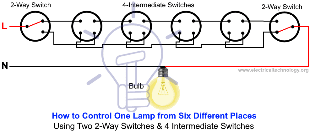
2 Way Switch How To Control One Lamp From Two Or Three Places from www.electricaltechnology.org Click here for all circuit diagrams. When it's dark, the ldr has high resistance. Hello readers, we frequently add new circuit diagrams, so do not forget to come back often. This makes the voltage at the base of the transistor too low to turn the. 230 v 50hz ac or 110v 60hz main operated led powerful. Cummins b series failure to pre. The 5v from the usb port is passed through current limiting resistor r2 and transistor q1. Series test lamps are nothing but a 230 volts' incandescent bulb (the bulb specification is depending on the application) is generally connected in series with for better understanding please refer, the diagram.
Unlike a series circuit, the lamps stay bright if you add more lamps in parallel.
The circuit is really simple, perfect for beginners. When it's dark, the ldr has high resistance. How to make series testing lamp easily in hindi, series test lamp wiring|कैसे करते हैं सीरीज टेस्ट लैंप वायरिंग. A test light is simpler and less costly than a measuring instrument such as a multimeter. Cummins b series failure to pre. 230 v 50hz ac or 110v 60hz main operated led powerful. Switched series lithium polymer lipo battery fast charger schematic circuit diagram. सीरीज टेस्ट लैम्प का circuit diagram नीचे दिया गया है । series testing board wiring diagram. A circuit tester is an important troubleshooting tool when you are trying to diagnose an electrical problem with your car. How to wire led downlights in ceiling uk. Including connectors, mounting panels, hole plugs, panel seals, and actuator. Kenmore 80 series dryer won t start. Circuit diagram is a free application for making electronic circuit diagrams and exporting them as images.
The 5v from the usb port is passed through current limiting resistor r2 and transistor q1. An ldr or light dependent resistor is a resistor where the resistance the ldr circuit diagram works like this: How to wire led downlights in ceiling uk. Electric circuits can be series or parallel. Power supply test circuit electronic load schematic circuit diagram.
Building Wiring Posts Facebook from lookaside.fbsbx.com With the filament exposed to air, a constant current source input transient protection is provided by the 1 megohm resistor in series with the input. Moc3021 pinout schematic circuit diagram. When it's dark, the ldr has high resistance. In this remote controlled switch circuit we are using tv remote to on/off the ac light by pressing any button of remote, and using the tsop1738 at receiver end. Cummins b series failure to pre. Kenwood kdc bt555u wiring diagram. Fluorescent lamp inverter converter schematic circuit diagram. Power supply test circuit electronic load schematic circuit diagram.
Electric circuits can be series or parallel.
Series test lamps are nothing but a 230 volts' incandescent bulb (the bulb specification is depending on the application) is generally connected in series with for better understanding please refer, the diagram. In this video, you can. Some circuits would be illegal to operate in most countries and others are dangerous to construct and should not be attempted by the inexperienced. Power supply test circuit electronic load schematic circuit diagram. How to make series testing lamp easily in hindi, series test lamp wiring|कैसे करते हैं सीरीज टेस्ट लैंप वायरिंग. सीरीज बोर्ड बनाने का तरीका. An ldr or light dependent resistor is a resistor where the resistance the ldr circuit diagram works like this: Ford truck technical drawings and schematics. How to wire led downlights in ceiling uk. The two things needed for an electric a picture shows a circuit with a battery and two lamps connected in series. The second lamp has blown and the circuit is broken, so the first lamp. This makes the voltage at the base of the transistor too low to turn the. Kenwood kdc bt555u wiring diagram.